
Self-Drilling Screws: Match the Point, Thickness and Driver
Choose self-drilling screws by material, drilling capacity, grip length and drive size. Learn when pilot holes are unnecessary and how to avoid point failure.
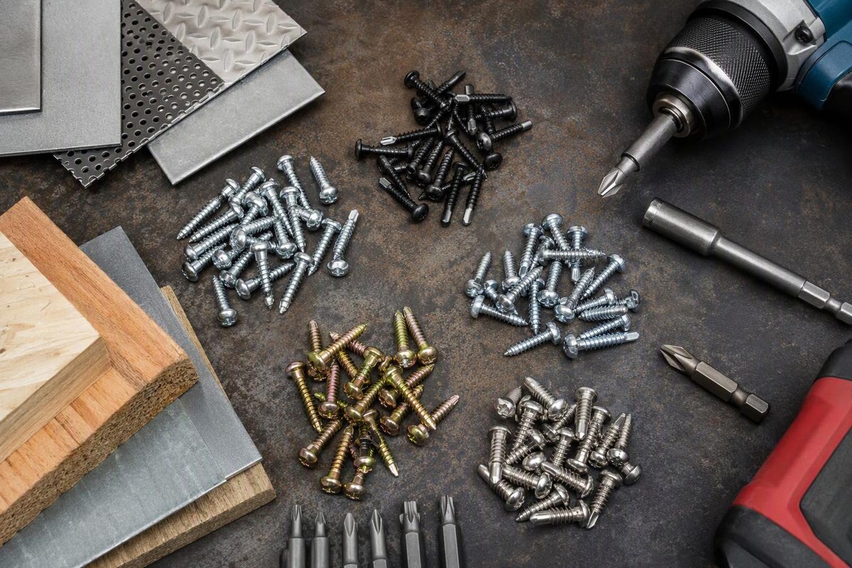
Self-drilling screws drill their own hole and form or cut mating threads—but only in materials and thicknesses the selected screw is designed to penetrate. Within that application, a separate pilot hole is normally unnecessary. Before choosing a length, check the substrate, drilling-capacity range and required thread protrusion. A longer screw does not automatically drill thicker steel. Simpson Strong-Tie’s selection guidance explains why the unthreaded point must finish drilling before the threads engage.
Identify the point and read the size
A self-drilling screw has a drill-bit-like point with cutting edges and flutes for removing chips. “Self-tapping” describes making mating threads; it does not, by itself, establish that the screw drills its own hole. Self-drilling screws perform both operations. See Simpson’s explanations of self-drilling tapping screws and drill-point features.
A sharp point is not equivalent to a drill point. Some sharp-point screws can pierce thin sheet without predrilling, but that is a separate, product-specific capability. For example, Teks distinguishes its sharp-point self-piercing screws from its drill-point screws.
For an inch-series designation such as #10-16 × 3/4 in.:
- #10 identifies the screw’s nominal diameter size—not the driver size.
- 16 means 16 threads per inch (TPI).
- 3/4 in. identifies length; confirm the measurement convention in the product drawing.
- #3 point, if listed separately, identifies the drill point—not a #3 Phillips recess.
These are separate specification fields in ICC-ES ESR-1271, Table 1. Record the head style, exact drive size, material/coating and model number too. Two screws with the same diameter and length are not necessarily interchangeable.
Match drilling capacity, not just the point number
These examples are all 3/4-in.-long Grabber hex-washer-head screws with #3 points, yet their specified drilling ranges differ:
| Model | Screw designation | Drill point | Steel drilling capacity, min.–max. |
|---|---|---|---|
| 08075H3 | #8-18 | #3 | 0.043–0.140 in. |
| 10075H3 | #10-16 | #3 | 0.043–0.175 in. |
| 12075H3 | #12-14 | #3 | 0.068–0.210 in. |
Source: Table 1 of ICC-ES ESR-1271, reissued July 2026. These are product-specific ranges, not a universal chart for every #3-point screw. The minimum thickness matters as well as the maximum.
Measure the metal thickness in inches or millimeters rather than relying only on a gauge label. For layered connections, also record the layer arrangement and any gaps. Simpson’s selection guidance accounts for total steel thickness and spacing between layers; do not treat a gap as irrelevant simply because the point cuts no metal there. Check the selected manufacturer’s definition of drilling thickness and grip length. Technical guidance.
Drilling capacity and usable grip are different checks. The screw must also be long enough to clamp the assembly while leaving the required threads beyond the supporting metal. ESR-1271 requires at least three exposed threads for its covered Grabber screws and lists minimum protrusion lengths. Follow the selected product’s instructions rather than counting the pointed tip as thread engagement.
Check material, head and exposure
- Steel-to-steel: Choose a screw explicitly rated for the steel thickness and grade. For structural work, verify the exact screw, connection-load data, spacing and applicable evaluation report—not merely that it can drill the steel. For example, ESR-1271’s connection-strength values apply to steel elements in direct contact; they do not establish capacity for a connection with a gap.
- Wood-to-steel: Look for a designated wood-to-metal fastener. Breakaway wings enlarge the hole through wood so the threads do not engage it prematurely and lift it away from the steel, a failure called jacking. Simpson’s guide explains the wing function.
- Stainless steel: Check both corrosion suitability and drilling capability. Simpson’s Type 305 and 316 self-drilling hex-washer-head screws are specified for aluminum and fiberglass, not steel. “Stainless” and “#3 point” do not establish steel-drilling compatibility.
Use a head that suits the bearing surface and required installed height. Confirm coating compatibility with the environment and adjoining materials. For more on stainless selection, see self-tapping stainless-steel screws.
Install without burning the point or overdriving
- Secure the work and check behind it. Allow for the protruding point and threads; wear eye protection against chips.
- Fit the exact bit or nut setter. Do not infer drive size from screw diameter. See matching driver bits.
- Use controlled rotation. Simpson recommends a drill motor rather than an impact driver or hammer drill to reduce point wear. Keep hammer action off and follow the screw’s specified speed.
- Drive square to the surface with steady pressure. More pressure is not necessarily better. For screws covered by ESR-1271, installation must be perpendicular using a variable-speed driving tool at no more than 2,500 RPM. Where the report and manufacturer instructions differ, the more restrictive requirement governs.
- Stop at the specified seating depth. Grabber’s pan-framing instructions define full seating as the head’s bearing surface flush with the work and recommend an adjustable nosepiece to prevent overdriving. Product instructions.
There is no universal installation RPM: Teks recommends 1,200–1,500 RPM for its wood-to-metal applications.
Works when / Fails when
Works when: the material, thickness range, grip, head and driver all match the selected fastener’s instructions.
Fails when: drilling cannot finish before thread engagement, chips become trapped, or excessive speed or pressure damages the point. If the screw stops cutting, stop driving and inspect it:
- Spins without making a hole: check forward rotation, material hardness and point damage.
- Worn or melted outer corners: reduce RPM within the manufacturer’s guidance.
- Split or chipped point: reduce applied pressure and recheck compatibility.
These symptoms and corrective actions come from Simpson’s troubleshooting guide. Do not compensate for an unsuitable screw by driving harder.