
Choose the Right Machine Screw for the Receiving Thread
Read inch and metric machine screw sizes, measure diameter and pitch, distinguish clearance from tap holes, and match length, head style and driver.
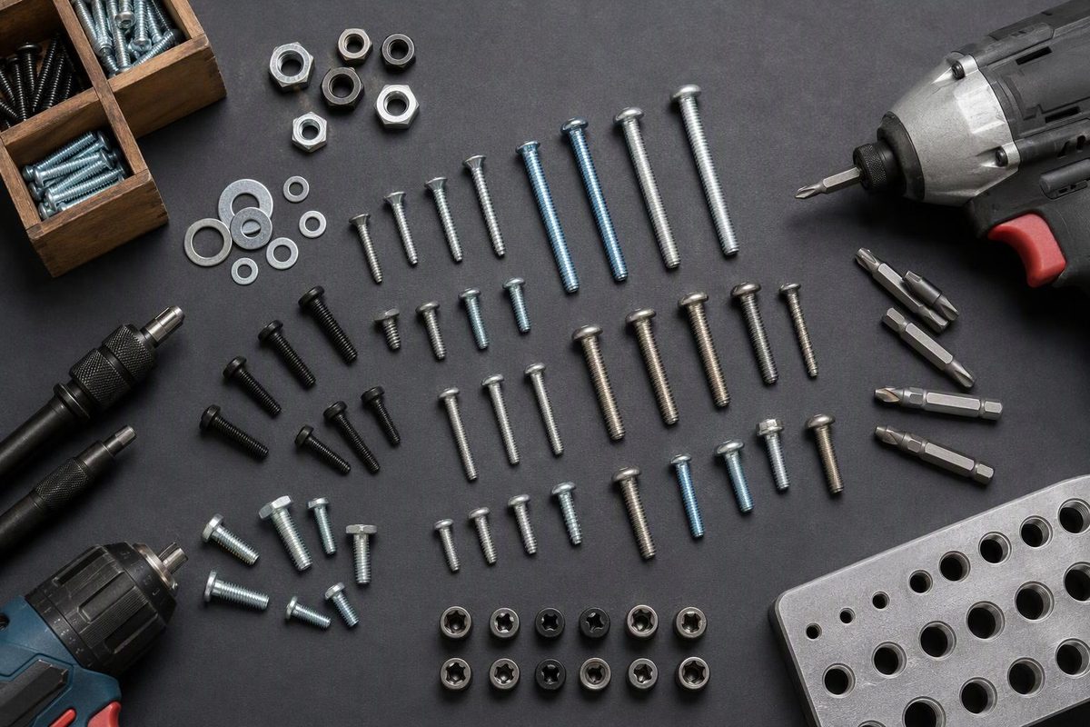
A machine screw normally fastens into a matching nut or an already-threaded hole. Choose it by thread system, diameter, pitch, length and head—not appearance alone. An ordinary machine screw is not intended to cut its own thread into an unthreaded hole; thread-cutting machine screws are a separate type, as Bolt Depot’s fastener type chart distinguishes.
Select a thread designation to check its nominal diameter and spacing—not its drill size.
Thread Designation Lookup
Without JavaScript, use the complete reference below.
- Nominal diameter
- 0.164 in.
- Thread spacing
- 32 TPI
US Unified coarse thread.
Match both diameter and spacing to the nut or threaded hole. These values do not specify a drill bit, driver or tightening torque.
Show All Reference Threads
| Thread | Diameter | Spacing | Series |
|---|---|---|---|
| #4-40 | 0.112 in. | 40 TPI | UNC |
| #4-48 | 0.112 in. | 48 TPI | UNF |
| #6-32 | 0.138 in. | 32 TPI | UNC |
| #6-40 | 0.138 in. | 40 TPI | UNF |
| #8-32 | 0.164 in. | 32 TPI | UNC |
| #8-36 | 0.164 in. | 36 TPI | UNF |
| #10-24 | 0.190 in. | 24 TPI | UNC |
| #10-32 | 0.190 in. | 32 TPI | UNF |
| #12-24 | 0.216 in. | 24 TPI | UNC |
| #12-28 | 0.216 in. | 28 TPI | UNF |
| M3 × 0.5 | 3 mm | 0.5 mm | Coarse |
| M4 × 0.7 | 4 mm | 0.7 mm | Coarse |
| M5 × 0.8 | 5 mm | 0.8 mm | Coarse |
| M6 × 1.0 | 6 mm | 1.0 mm | Coarse |
Sources: Bolt Depot’s nominal machine-screw diameter, Unified thread and metric thread-pitch tables, linked in the article.
A screw that enters a hole is not necessarily the correct screw. Diameter and pitch must both match the receiving thread. Forcing similar-sized but incompatible threads can damage the screw, nut or threaded part. Accu’s cross-threading guide explains this failure.
Read Diameter, Thread Spacing and Length Separately
Machine-screw size descriptions put diameter, thread count or pitch, then length in that order:
- #8-32 × 1/2 in. means a US numbered diameter of #8, 32 threads per inch (TPI), and a nominal length of 1/2 in.
- M4 × 0.7 × 12 mm means a metric nominal diameter of 4 mm, a pitch of 0.7 mm between adjacent threads, and a nominal length of 12 mm.
US Unified threads use TPI; metric threads use pitch in millimetres. These describe thread spacing in different ways and are not interchangeable size labels. Bolt Depot’s notation guide explains both systems.
Common US Sizes Have Coarse and Fine Threads
| Size | Nominal Diameter (in.) | UNC (TPI) | UNF (TPI) |
|---|---|---|---|
| #4 | 0.112 | 40 | 48 |
| #6 | 0.138 | 32 | 40 |
| #8 | 0.164 | 32 | 36 |
| #10 | 0.190 | 24 | 32 |
| #12 | 0.216 | 24 | 28 |
Sources: Bolt Depot’s nominal machine-screw diameters and Unified thread table. UNC denotes coarse threads; UNF denotes fine threads. These are identification dimensions, not drill-bit recommendations.
Common Metric Coarse Sizes Still Require a Pitch Check
| Thread Designation | Nominal Diameter (mm) | Pitch (mm) |
|---|---|---|
| M3 × 0.5 | 3 | 0.5 |
| M4 × 0.7 | 4 | 0.7 |
| M5 × 0.8 | 5 | 0.8 |
| M6 × 1.0 | 6 | 1.0 |
Source: Bolt Depot’s metric thread-pitch table. For a replacement, verify pitch rather than assuming a listing with only “M4” gives the complete specification.
Measure the Threads, Not the Head
Measure across the outside thread crests with calipers and compare the result with the nominal diameter. Head diameter does not identify thread size.
Check pitch with a thread-pitch gauge. On a short screw, this is more practical than trying to count a full inch of threads. Bolt Depot’s TPI and pitch measurement guide recommends a thread gauge for this measurement.
Measure length from the correct reference point. Pan and other above-surface heads are generally measured from under the head to the tip. A flat countersunk screw is generally measured from the top of the head to the tip. Use the product drawing for unusual head forms. Bolt Depot’s length measurement reference shows the distinction.
Record the head, drive, material and special features as well. A locking patch, captive washer or special point can be part of the required replacement specification.
For equipment repair, use the manufacturer’s part specification where available. Measurements identify likely candidates; they do not establish an equivalent strength grade or approved replacement.
Match the Hole: Clearance Is Not a Tap Hole
A machine-screw joint commonly needs different hole functions:
| Receiving Feature | Function | Check |
|---|---|---|
| Clearance hole | Passes the screw through an unthreaded part | Diameter and required fit |
| Tap-drilled hole | Leaves material for a tap to create threads | Exact thread, tap type and material |
| Threaded hole or nut | Engages the screw’s thread | Diameter, pitch and usable engagement |
For example, TR Fastenings recommends 3.3 mm for tapping the standard M4 × 0.7 thread, but 4.5 mm for its M4 clearance hole. The smaller hole must still be tapped before accepting an ordinary M4 machine screw. These are chart recommendations, not universal dimensions for every joint. See the TR tapping and clearance chart.
Do not transfer a tap-drill value to a thread-forming process without checking the tool instructions. OSG provides dedicated pilot-hole recommendations for its thread-forming taps. Once the required diameter is established, use the drill-bit sizes chart to compare available bit dimensions.
For wood, plan a connection using a suitable nut or threaded insert rather than treating ordinary machine threads as wood-screw threads. Select an insert for the wood type and load, and follow its specified drill size and installation instructions. E-Z LOK’s wood-insert guide describes these selection factors.
Match the Head, Driver and Installed Length
Head style and drive are separate features. Pan describes the head shape; Phillips describes the recess. A replacement must fit both the mounting surface and the tool, a distinction covered by Bolt Depot’s notation guide cited above.
For an above-surface head, check head diameter, bearing surface and surrounding clearance. For a countersunk head, match the screw drawing to the recess; see fitting a countersunk flat-head screw.
Use the exact recess profile and bit or key size. Thread diameter alone does not identify the driver.
Choose length to account for the parts and washers being clamped, required thread engagement and clearance behind the joint. In a blind hole—a hole that does not pass through the part—the screw must not bottom out before clamping the parts.
Material, grade and coating also belong in the specification. A same-sized screw of a different material is not automatically an equivalent replacement.
Start by Hand and Stop at Unexpected Resistance
Align the screw squarely and start it by hand before applying powered torque. If it binds immediately, remove it and check alignment, pitch, debris and thread damage. Do not use an impact driver to force a doubtful thread match. Hand assembly makes the increasing resistance of cross-threading easier to detect, as Accu’s guidance cited above explains.
Finish with the tool and tightening torque specified for the assembly—not a torque guessed from screw diameter alone. Torque selection also depends on fastener strength, geometry and friction, as shown in Bossard’s torque and preload guidance. The reference dimensions here do not supply an assembly-specific torque or required engagement length.
Before ordering, write the complete requirement: for example, M4 × 0.7 × 12 mm, Phillips pan head, specified material/grade and coating, plus any required washer or locking feature.