
How to Choose a Flush-Fitting Screw—and Make It Sit Properly
For a reliable flush fit, define the installed height, use the selected screw's drawing, match the countersink and test a representative sample.
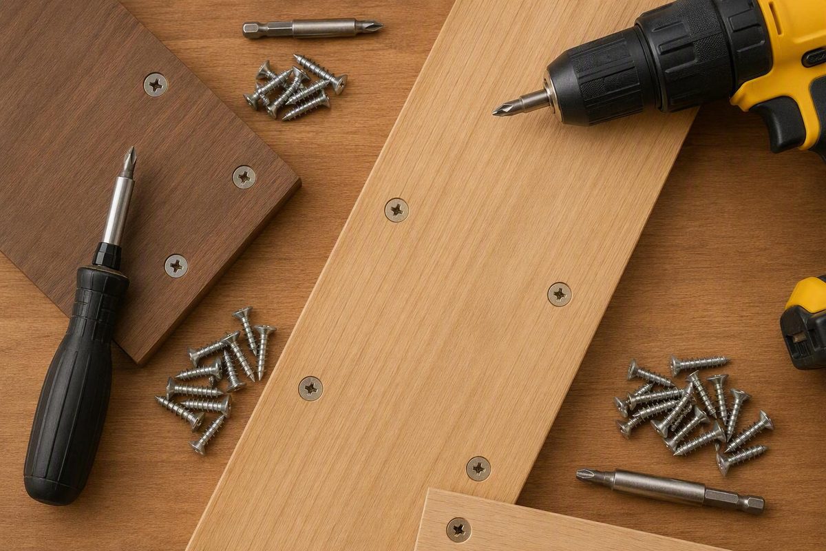
A countersunk flat-head screw is intended to finish flush with, or slightly below, a work surface. That result is not guaranteed by the words “flat head.” It depends on whether the screw’s head geometry, the prepared recess, the clearance or pilot hole, and the required installed height are compatible.
This is general selection and troubleshooting guidance, not a dimensional standard. Treat flushness as a fit-and-tolerance requirement: define where the head must finish, identify the governing screw specification or manufacturer drawing, prepare a matching recess, and test a representative sample before altering a finished part or machining a production batch.
What a countersunk flat-head screw is
A countersunk flat-head screw has a tapered or conical underside intended to seat in a matching conical recess. When the head and recess fit correctly, the flat top of the head can finish level with the surrounding surface or below it. This differs from a pan, round, button, or socket-cap head, which ordinarily remains above the surface.
“Flat head” describes the head shape and intended installed profile, not the drive used to turn the screw. Flat heads are sold with internal hex, Phillips, Pozidriv, Torx or other six-lobe drives, straight slots, security drives, and other drive forms. Industrial catalog filters list flat-head screws across multiple drives, materials, thread systems, and countersink angles, confirming that head geometry and drive geometry are separate selection decisions (McMaster-Carr’s countersunk-head machine-screw catalog).
Retailers frequently use “flat head,” “countersunk,” and “flush-fit” together. In ordinary buying language, all three may indicate a screw intended not to project above the work. The labels do not prove that two products have identical head angles, diameters, edge shapes, under-head radii, tolerances, or undercut geometry.
Related profiles include:
- Standard flat head: A conical underside with a substantially flat top, intended for a fully flush or recessed installation.
- Oval or raised countersunk head: A tapered underside that enters a countersink, plus a rounded or decorative portion that remains above the surface.
- Bugle head: A countersunk-style profile commonly associated with drywall, wood, or decking applications rather than a standard precision flat-head profile.
- Undercut flat head: A reduced-height variation that may permit a shallower recess or additional thread engagement in certain short screw sizes.
- Alternative-angle flat head: A profile intended for a corresponding alternative-angle countersink, sometimes used where a shallower recess is required.
- Non-countersunk head: A pan, button, round, truss, hex, or cylindrical cap profile that bears on the surface instead of entering a conical seat.
A countersunk flat-head screw can sit flush when the recess matches the selected screw. The name alone is not a promise of flushness.
The following conceptual cross-section identifies the important features. It is intentionally non-dimensional:
                  head top
          ─────────────────────
/
/ ← conical underside
α /
work surface ───\────────/────────────
/ ← countersink
/
                   |  |
                   |  |  ← clearance or pilot hole
                   |  |
                   |  |

          <---- head diameter ---->

α = included head angle
Intended installed height = head top relative to work surface
The included angle is measured across the tapered seating surface, not from one side of the cone to the screw axis. Head diameter, recess diameter and depth, hole diameter, edge geometry, under-head geometry, coatings, and tolerances can all influence where the top finally lands.
Where a flush head helps—and where another head may be better
The main reasons to choose a countersunk flat head are surface clearance, reduced snagging, and appearance.
A flush head can be useful on removable panels, machine parts, close-clearance equipment, furniture, cabinets, flooring, woodwork, and fabricated metal components. It can prevent nearby objects or materials from catching on a projecting head and can leave an uninterrupted visible surface. Retail flat-head socket-screw listings identify removable panels, machine parts, fixturing, and close-tolerance machinery as applications in which head clearance matters (Monster Bolts’ metric flat-head socket-screw collection).
A flush profile is not automatically better. A pan, round, button, truss, or socket-cap head may be appropriate when the head can remain above the surface. Avoiding a countersink can simplify preparation, leave more material around the hole, or provide a head with more room for driver engagement.
Raised countersunk and oval heads occupy the middle ground. Their tapered undersides use conical seats, but their rounded upper portions remain visible. They suit applications that call for a softened or decorative appearance rather than a completely flat surface.
Countersunk designs involve several tradeoffs:
- Forming the seat removes material from the part.
- The recess must be concentric with the hole and compatible with the selected head.
- Thin stock may not provide enough depth for the required recess.
- Head and recess tolerances can complicate exact installed-height control.
- The shallow head may limit the available depth of the drive recess.
- Commercial engineering guidance indicates that countersunk heads generally accept less installation torque than cap or button heads, although the actual limit depends on the specific screw and joint (Accu’s guide to screw-head types).
Consider another head when the joint needs a larger bearing area, deeper driver engagement, frequent access, simpler preparation, or preservation of a thin section. A non-countersunk head may be more practical when protrusion is acceptable.
Those properties depend on the complete fastener specification, material and grade, thread engagement, joint design, environment, installation condition, and applicable engineering requirements.
The complete selection checklist
Select the screw in a deliberate order. Starting with the drive style—or whichever package is locally available—can leave essential requirements unresolved.
1. Application and required installed height
Define what “flush” means for the project:
- Exactly level with the surrounding surface
- Slightly recessed
- No higher than a stated clearance envelope
- Visually unobtrusive without a precision height requirement
Also establish whether the screw will be removed regularly, whether the driver can approach it squarely, and whether the material can accommodate the recess without becoming unacceptably thin.
2. Governing drawing or specification
Determine whether the assembly is controlled by a product drawing, manufacturer specification, recognized fastener standard, customer requirement, or existing mating part. Record the revision where applicable.
Do not assume that two screws described as “flat-head M6” or “10-32 countersunk” are dimensionally equivalent. A controlled document should establish the head profile, angle, key dimensions and tolerances, thread, material, mechanical properties, and coating requirements.
Some retailers associate metric flat-head socket screws with DIN 7991, but a retailer’s category label is not proof of current compliance, dimensional equivalence, or suitability. Request the applicable standard, a controlled manufacturer drawing, or a declaration that identifies exactly what is being supplied.
When comparing sellers, ask for:
- A drawing number and revision
- The dimensional or product standard claimed
- Material grade or property class
- Finish or coating specification
- Lot identification or certificates, if required
- The seller’s substitution policy
- Confirmation that supplied alternatives retain the required head geometry
3. Thread system
Choose inch or metric threading according to the mating component. Confirm the complete thread designation rather than identifying the screw by apparent diameter alone.
For a machine screw, the screw and tapped hole or nut must have compatible thread forms. For a wood, tapping, self-drilling, or thread-forming screw, the substrate and installation method also govern hole preparation and engagement.
4. Nominal diameter and pitch
Specify both diameter and pitch or threads per inch. A nominal diameter alone does not communicate every necessary thread feature.
For example, one marketplace listing describes an M6 × 18 mm flat-head socket screw and states a 1.0 mm pitch. The designation communicates a nominal diameter and length, but the listing does not state the stainless grade, property class, countersink angle, dimensional standard, or manufacturing tolerances (the seller-listed M6 × 18 mm socket screw). Those omissions matter when fit or performance is controlled.
5. Length
Specify the required length and verify how it is defined under the applicable product specification. Do not apply an assumed measurement convention to every flat-head screw, specialty profile, or product family.
Evaluate length against the actual joint stack. The screw must provide the required engagement without bottoming in a blind hole, interfering with nearby parts, or extending beyond the permitted envelope. Account for inserts, unthreaded portions, and thread runout where applicable.
6. Head profile and angle
State whether the screw is standard flat, undercut flat, alternative-angle flat, oval, raised countersunk, bugle, or another profile. Include the required angle and enough drawing information to prevent substitution based only on a similar product description.
7. Drive
Choose the drive according to tool access, assembly method, service access, appearance, and purchasing compatibility. Internal hex, Phillips, Pozidriv, Torx, slotted, and security drives can all appear in countersunk heads.
The available evidence does not support a universal ranking for torque capacity, cam-out, or stripping resistance. Those outcomes depend on screw size, recess dimensions, tool fit, hardness, installation alignment, and applied load. Obtain the exact driver type and size, particularly when similar-looking cross-recess or six-lobe systems are involved.
8. Material and grade or property class
Material identity and fastener performance are separate specifications. Catalogs list countersunk screws in steel, stainless steel, brass, aluminum, titanium, and plastic, but a base-material name alone does not establish strength, ductility, temperature capability, wear resistance, or corrosion suitability.
Specify the grade, alloy, condition, or property class where performance matters. “Stainless” alone is not enough to qualify a screw for wet, marine, chemical, structural, or high-temperature service.
9. Finish or coating
Identify the required finish or coating separately from the base material. Coatings on the screw or workpiece may also contribute to installed-height variation when tolerances are tight.
10. Quantity, inspection, and traceability
For a one-off repair, quantity may be the main commercial issue. Production work may require lot traceability, certificates, controlled suppliers, sample inspection, first-article approval, or lot-specific dimensional checks.
Catalog filters are useful for discovering possible combinations of angle, drive, material, thread, and size. They do not prove that every filtered attribute is available in every combination.
Copyable procurement checklist
- Specification or drawing and revision:
- Thread system, nominal diameter, and pitch/TPI:
- Length and applicable measurement convention:
- Head profile:
- Included head angle:
- Drive type and size:
- Material, grade, alloy, or property class:
- Finish or coating:
- Required installed-height tolerance:
- Quantity:
- Lot, certificate, or traceability requirements:
- Mating material and service environment:
- Approved manufacturers or substitution restrictions:
Head angles: 82°, 90°, 100°, and the exceptions
The head angle is the included angle of the tapered seating surface. The countersink must match that angle unless the governing design explicitly requires another seating arrangement.
Commercial head-style guidance associates an 82-degree standard flat head with many inch-series products, a 90-degree flat head with many metric products, and a 100-degree flat head with certain thin-material applications. These are useful identification clues, not universal rules; the actual screw specification governs (Fastener SuperStore’s screw-head guide).
| Nominal included angle | Common association | Selection warning |
|---|---|---|
| 82° | Many inch-series flat-head screws | Not every inch screw uses this angle |
| 90° | Many metric flat-head screws | A metric designation alone does not prove the angle |
| 100° | Some thin-material and aviation-oriented designs | Not interchangeable with an 82° or 90° seat |
| 60° and other angles | Specialty products and catalog exceptions | Confirm the drawing and intended application |
Industrial catalog filters include 60-, 82-, 90-, and 100-degree options. That demonstrates the range of listed selection attributes, not a universal standard or guaranteed availability of every angle with every material, drive, and thread combination (McMaster-Carr’s catalog filters).
When the angles differ, the tapered surfaces do not seat uniformly. Contact may begin near the outer edge or close to the hole instead of across the intended seating surface. Tightening harder does not correct incompatible geometry.
Even equal nominal angles do not ensure exact flushness. Final position can change with:
- Head diameter
- Countersink mouth diameter
- Countersink depth
- Clearance-hole diameter
- Under-head radius
- Head-edge radius or chamfer
- Coating thickness
- Burrs or debris
- Concentricity
- Screw and recess tolerances
For a comparable opening, a wider included angle creates a shallower cone. Alternative-angle and undercut designs may therefore be considered when a standard recess would remove too much depth or when certain short screws require more usable thread engagement. They are not automatically interchangeable with standard heads: profile, bearing geometry, drive depth, dimensions, and the applicable specification may differ.
Before machining production parts, inspect or measure a representative screw and obtain its drawing. If the job has a controlled installed-height tolerance, use the specified dimensions and inspection method rather than a universal countersink-depth formula.
Preparing the hole and countersink
The exact preparation depends on the screw design, substrate, thread engagement, tooling, and manufacturing method. A machine screw passing through a clearance hole into a nut is not prepared like a wood screw entering hardwood, and neither necessarily uses the same process as a self-drilling or thread-forming screw.
Within those limits, use this controlled sequence:
- Confirm the screw and installed-height requirement. Check the thread, head profile, angle, diameter, under-head geometry, and governing drawing.
- Secure and support the workpiece. Prevent movement and support thin or flexible material appropriately.
- Make the required pilot or clearance hole. Use the diameter and process specified for the screw, substrate, and joint.
- Form a concentric countersink. Match the tool angle to the selected screw and control the recess by the specified diameter, depth, or inspection feature.
- Remove chips and burrs. Clean the countersink and hole.
- Inspect the recess. Check angle, size, concentricity, finish, and remaining material.
- Insert a sample screw. Examine initial seating without forcing the head into place.
- Use the correct driver. Seat the bit fully and keep it aligned with the screw axis.
- Stop at the specified installed height. Do not continue merely because the driver can still turn.
Not every countersunk screw requires a separately drilled pilot hole followed by a separate countersinking operation. Some screws cut, form, or drill aspects of their own holes, while production processes may combine operations. Follow the instructions for the selected fastener, substrate, and tooling.
Countersink diameter and depth should come from the actual fastener specification, manufacturer drawing, or controlled assembly requirement. A shallow or undersized recess can leave the head proud. An excessively deep or oversized recess can place it too low, remove unnecessary material, or leave less support around the seat.
Test a sample fastener before repeating the operation across multiple parts. In precision work, use a production-lot screw rather than an unverified look-alike because geometric variation can affect final height.
Do not apply a generic installation torque to an unspecified countersunk screw. Required torque or preload depends on material and grade, coating, lubrication, thread condition, engagement, joint stiffness, and application requirements. Commercial machining guidance identifies overtightening and uncontrolled countersinking as installation risks and recommends specification-based torque and controlled workholding rather than forced seating (Okdor’s countersinking-error guidance).
Tooling, cutting speed, lubrication, feed, and workholding must suit the material and machine. Follow the tool and machine manufacturers’ instructions, secure the workpiece, keep hair, clothing, jewelry, cords, and other loose items away from rotating equipment, and use protective practices appropriate to the machine, chips, dust, tool, and work material.
Why the head sits proud, too deep, or crooked
A seating problem can result from geometry, preparation, alignment, contamination, or tolerance variation. More tightening force should not be the first diagnostic response.
| Symptom | Likely checks | Low-risk next steps |
|---|---|---|
| Head sits proud | Countersink too shallow or small; wrong angle; clearance-hole interference; burrs or debris; under-head geometry contacting the hole; coating buildup; misalignment; dimensional variation | Clean and inspect the seat; compare the screw drawing with the recess; measure the hole and countersink; test another screw from the same lot |
| Head sits too deep | Countersink too deep or large; different head profile used; installed-height requirement not defined; part prepared for another screw | Verify the screw identity and drawing; measure the recess; compare with an approved sample; stop until the required height is defined |
| Head is tilted or uneven | Hole and countersink not concentric; debris under one side; damaged seat; driver held off-axis; joint pulling the screw sideways | Disassemble and clean; inspect contact marks; check concentricity and joint alignment; reproduce the condition on a test piece |
| Head rocks before tightening | Angle mismatch; irregular seating surface; incompatible profile or radii | Confirm both included angles and profiles; inspect with a known sample; do not use tightening force to reshape the seat |
| Drive slips before seating | Wrong or worn bit; shallow engagement; misalignment; excessive resistance; head or recess mismatch | Use the exact driver type and size; identify the source of resistance; correct alignment before continuing |
| Fit varies among screws | Lot or manufacturer variation; coating variation; mixed products; recess variation | Segregate lots; inspect representative samples; confirm the supplier and specification; record installed-height measurements |
Proud heads
Start with the recess. Is it deep and wide enough for the actual head? Then check angle compatibility, clearance-hole diameter, burrs, debris, coatings, and concentricity.
A tight clearance hole may interfere with the head-to-shank transition before the cone reaches its intended seat.
Heads below the intended surface
An over-deep or oversized countersink is one possible cause of a head finishing too low. A smaller or different head profile can produce the same symptom. First determine whether the requirement was “exactly flush,” “slightly recessed,” or simply “below a clearance line.”
Do not improvise a correction until the intended bearing and installed-height requirements are known. If the recess is already oversized, the repair must be evaluated against the part drawing and joint requirements.
Tilted heads
Examine the contact pattern instead of continuing to tighten. Uneven seating can mark the surface without establishing the intended fit.
Tolerance stack-up
Two components can share the same nominal angle and still produce different installed heights. The stack can include head diameter and height, radii, edge geometry, coating, clearance-hole diameter, countersink diameter and depth, concentricity, and the tolerance on each feature.
Manufacturer or lot variation can therefore matter. In one machining-forum case involving finished anodized parts, changing screw brands reportedly lowered the installed head by about 0.010 inch and provided the required clearance, but the replacement still was not exactly flush. The report is anecdotal and does not establish that changing brands will produce a predictable correction (the Practical Machinist seating discussion).
Prioritize reversible checks:
- Clean and inspect the recess.
- Test another screw from the same lot.
- Confirm that packages or bins have not been mixed.
- Compare the screw and part with their drawings.
- Measure the clearance hole and countersink.
- Inspect an approved alternative from a compliant supplier.
- Reproduce the condition on scrap or a test coupon.
Deepening a countersink in a finished part is irreversible. It changes the machined geometry and may affect remaining thickness, finish, conformity, support, and final head position. Machining the screw head can also affect dimensional conformity, finish, and driver engagement.
Forum participants discussing head machining specifically warned that reducing head thickness also reduces engagement between the tool and drive recess, potentially increasing slipping or stripping. That observation is anecdotal rather than a quantified engineering limit, so any such modification should receive application-specific review where fit, load, traceability, or safety matters (the forum’s head-modification discussion).
Countersink, counterbore, and alternative flat-head profiles
A countersink is a conical recess for a tapered head. A counterbore is a cylindrical, flat-bottomed recess commonly used to sink a cylindrical head below the work surface.
The drive does not determine the recess. An internal-hex flat-head screw still has a tapered underside and requires a countersink. An internal-hex socket-cap screw has a cylindrical head and commonly uses a flat bearing surface or counterbore when it must be recessed.
| Head or recess type | Intended installed profile | Seat form |
|---|---|---|
| Standard flat head | Flat or recessed when correctly matched | Conical countersink matching the head |
| Undercut flat head | Flat or recessed with reduced head height in applicable designs | Profile-specific countersink |
| Alternative-angle flat head | Flat or recessed with a correspondingly different cone | Countersink matching the specified angle |
| Oval or raised countersunk | Rounded portion remains above the surface | Conical countersink beneath the raised top |
| Bugle head | Near or below the surface in a suitable substrate | Seat appropriate to the screw and material |
| Pan, button, or round head | Head remains above the surface | Flat bearing surface rather than a conical seat |
| Socket-cap head | Cylindrical head above the surface or recessed | Flat surface or cylindrical counterbore |
An undercut flat head may permit shallower countersinking or provide additional usable thread engagement in some short screw sizes. It is a specialized profile, not a universal lower substitute for a standard flat head.
A wider-angle flat head creates a shallower cone than a narrower-angle head for a comparable opening. It may be considered where material depth is limited, but only when the part design and fastener specification support that geometry.
Oval and raised countersunk screws use tapered undersides but intentionally leave rounded tops above the surface. They do not provide the same completely flat clearance profile as a standard flat head.
If flushness is unnecessary, a pan, button, or socket-cap head may avoid a deep conical recess. The appropriate choice still depends on available space, tool access, material thickness, bearing requirements, required preload, and the complete joint design.
A final choose-and-check workflow
Use this sequence before ordering fasteners or cutting the workpiece.
1. Define the surface requirement
State whether the head must be:
- Exactly flush
- Slightly recessed
- Below a specified clearance envelope
- Merely free of unacceptable projections
Do not let “flat head” substitute for a measurable installed-height requirement.
2. Decide whether countersinking is appropriate
Check material thickness, edge location, available support, surface finish, and production method. If the recess would remove too much material, investigate an approved undercut or alternative-angle design—or reconsider whether a projecting head is acceptable.
3. Identify the joint and thread requirements
Confirm the thread system, diameter, pitch or TPI, engagement, mating component, length, and joint stack. Establish whether the application requires a machine screw, wood screw, tapping screw, self-drilling screw, or another fastener family.
4. Select head profile and drive independently
Choose the head profile according to installed height and seat geometry. Choose the drive according to tool access, service needs, assembly method, and purchasing compatibility.
5. Specify material, grade, and coating
Do not infer strength or corrosion suitability from “stainless,” “brass,” “titanium,” “aluminum,” or “steel” alone. Identify the grade, property class, coating, service environment, and mating materials where performance matters.
6. Obtain the standard or manufacturer drawing
Before production machining, confirm:
- Included head angle
- Head diameter
- Head height or complete profile
- Edge and under-head radii
- Clearance-hole requirement
- Countersink diameter
- Countersink depth or other controlled feature
- Dimensional tolerances
- Allowable installed-height tolerance
7. Match the recess to the screw
Use the appropriate pilot or clearance hole and a concentric countersink matching the actual head. Control the operation from the applicable drawing rather than a generic rule.
8. Test a production-representative sample
Use a screw from the intended manufacturer and lot when possible. Test it in scrap, a coupon, or a first article before repeating the operation. Inspect where the cone contacts the seat and where the top finishes.
9. Inspect the completed installation
Confirm that the head reaches the required position without forced seating, rocking, tilting, drive damage, or unacceptable removal of material.
Stop and escalate when necessary
General fastener guidance is not sufficient for structural, fatigue-critical, aerospace, medical, lifting, pressure-containing, anti-ligature, or other regulated and safety-critical uses. Obtain application-specific engineering approval, controlled specifications, and the required inspection plan before selecting or modifying the screw or recess.
Field checklist
- [ ] The sample screw matches the specified thread, head profile, and angle.
- [ ] The correct, undamaged driver is available.
- [ ] The hole and countersink are clean, concentric, and free of burrs.
- [ ] The head reaches its specified height without forced seating.
- [ ] The clearance hole does not interfere with the under-head transition.
- [ ] Sufficient material remains beneath and around the countersink.
- [ ] Material grade, coating, and environment have been evaluated separately.
- [ ] No finished part or screw head is irreversibly modified before the specification is confirmed.
Frequently asked questions
Are flat-head and countersunk screws the same thing?
They are often used as equivalent retail terms for a screw with a tapered underside intended to finish flush. More precisely, “countersunk” describes how a tapered head seats in a conical recess, while “flat head” identifies a countersunk profile with a substantially flat top.
Not every countersunk screw is a standard flat head. Oval, raised countersunk, bugle, undercut, and alternative-angle heads are related but geometrically distinct. Confirm the actual profile and dimensions rather than assuming similarly labeled products are interchangeable.
Should I use an 82-degree or 90-degree countersink?
Use the angle specified for the actual screw. Many inch-series flat heads are associated with an 82-degree included angle, while many metric flat heads are associated with 90 degrees, but both conventions have exceptions. Commercial guides also identify 100-degree alternatives for certain applications (Fastener SuperStore’s head-style guide).
Do not choose by thread system alone. Check the product drawing, specification, or a verified sample, then use a matching countersink. Matching nominal angles still does not resolve differences in head diameter, recess depth, radii, clearance, coatings, and tolerances.
Why is my flat-head screw still above the surface?
Possible causes include an undersized or shallow countersink, an angle mismatch, a tight clearance hole, burrs or debris, interfering under-head geometry, coating buildup, poor concentricity, or dimensional variation in the screw.
Clean and inspect the seat first. Compare the screw and recess with their drawings, measure the hole and countersink, and try another compliant sample before removing more material. Tightening harder can force or damage components without correcting incompatible geometry.
What is the difference between a countersink and a counterbore?
A countersink is a conical recess for a tapered screw head. A counterbore is a cylindrical, flat-bottomed recess commonly used when a cylindrical head must sit below the surface.
An internal-hex drive can appear in either head style. A flat-head internal-hex screw needs a countersink; a cylindrical socket-cap screw ordinarily needs a flat bearing surface or counterbore.
Can I deepen the countersink or grind down the screw head?
Possibly, but neither should be the first response. First verify the fastener identity, drawing, angle, recess dimensions, clearance hole, burr condition, and required installed height. Test a compliant alternative or reproduce the fit on scrap.
Deepening the recess removes additional material and changes the finished geometry. Machining the head changes the fastener’s dimensions and can reduce drive-recess engagement. Treat either action as an engineering decision when the part is finished, load-bearing, regulated, traceable, or dimensionally controlled.
“Flat head” describes an intended profile, not a guarantee of fit. A reliable flush installation comes from defining the required installed height, obtaining the selected screw’s specification or drawing, matching the countersink to its actual geometry, and testing a representative sample. Resolve angle, diameter, depth, clearance, alignment, and tolerance problems before altering a finished part. For load-bearing or regulated assemblies, use application-specific engineering requirements rather than general fastener guidance.