
Socket Head Cap Screw: Match the Thread, Head Space and Driver
How this site is written
Dimensions and compatibility depend on the exact fastener, material, tool, and manufacturer. We show the matching logic and name the source; verify the packaging and tool manual before drilling or driving.
Identify a socket head cap screw, check metric head and hex-key sizes, choose the right seating hole, and avoid unsafe substitutions or tightening.
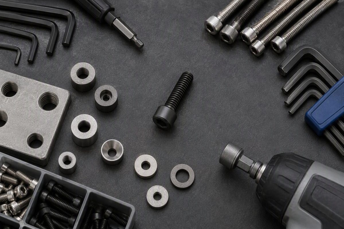
A standard socket head cap screw has a cylindrical head, a flat bearing surface underneath and an internal hex socket for an Allen key or hex driver bit. Its head can stand above the work or sit in a counterbore. The internal drive avoids the side clearance needed to turn a wrench around an external hex head, but you still need access to insert and operate the hex tool. Unbrako’s engineering guide describes both protruding and counterbored installations.
Measure screw length from underneath the head to the tip—not over the head. Measure thread diameter across the outside of the threads. Neither measurement tells you the hex-key size. Bolt Depot’s socket-cap reference shows these measurement points.
The standard machine-threaded type needs a matching tapped hole or nut; do not treat it as a self-drilling or wood screw.
Identify the size and the standard-height head
For a replacement, record the thread diameter and pitch, under-head length, head dimensions, material or strength specification, and whether the shank is fully or partly threaded.
- M6 × 1.0 × 20 mm: 6 mm nominal thread diameter, 1.0 mm pitch and 20 mm under-head length.
- 1/4-20 × 1 in.: 1/4 in. nominal thread diameter, 20 threads per inch and 1 in. under-head length.
Metric pitch and inch threads per inch are different ways of describing thread spacing. Do not substitute a nearby inch size for a metric screw. For the broader identification method, see how to measure machine-screw threads.
Common metric head and driver dimensions
These values come from Unbrako’s DIN 912 / ISO 4762 stainless socket-head cap-screw sheet. They apply to the listed standard-height head, not automatically to button-head, low-head or countersunk socket screws.
| Thread size | Coarse pitch (mm) | Head diameter, maximum (mm) | Head height, maximum (mm) | Hex-key size (mm) |
|---|---|---|---|---|
| M3 | 0.50 | 5.5 | 3.0 | 2.5 |
| M4 | 0.70 | 7.0 | 4.0 | 3.0 |
| M5 | 0.80 | 8.5 | 5.0 | 4.0 |
| M6 | 1.00 | 10.0 | 6.0 | 5.0 |
| M8 | 1.25 | 13.0 | 8.0 | 6.0 |
These are screw dimensions, not drill or counterbore sizes. Use the selected product’s drawing and the assembly’s hole specification before machining. An M6 screw in this table takes a 5 mm hex key—not a 6 mm key.
Choose the seating hole, not just the thread hole
A socket head cap screw presents three separate fit questions:
| Feature | What it must accommodate |
|---|---|
| Clearance hole in the clamped part | The screw body or threads passing through without engaging |
| Tapped hole or nut | The exact thread system, diameter and pitch |
| Counterbore, if required | The cylindrical head, its flat bearing seat and installation clearance |
A counterbore is a cylindrical, flat-bottomed recess for the head. A conical countersink is not a substitute for that seat. If the design requires a conical flush-head fastener, use the specified countersunk flat-head screw instead.
Check that the head bears on the seat rather than hanging up on an edge. The small radius where the shank meets the head also needs clearance. Unbrako’s hole-preparation guidance warns that an unsuitable sharp edge can prevent proper seating or damage this fillet; excessive chamfering reduces bearing area. A specified edge-breaking chamfer is different from a countersink intended to seat a conical head.
Recessing the head also changes the length calculation. In a simple plate-to-tapped-part assembly, measure the clamped thickness from the counterbore floor, not from the plate’s top surface. Recheck penetration and bottom clearance: the same screw reaches farther into the tapped part after its head is recessed. Do not add or deepen a counterbore in an existing load-bearing assembly without checking the design.
Required thread engagement depends on the receiving material’s strength. A strong screw does not prevent a weak tapped hole from stripping, and partly threaded screws need their unthreaded body checked against the joint geometry. Unbrako’s joint-design guidance treats these as assembly-specific checks.
Select the material without changing the joint’s rating
Do not infer strength from the head shape or black finish. Unbrako lists a metric alloy-steel socket-head cap screw in property class 12.9, while its stainless sheet includes A2/A4-70 and A2/A4-80. The manufacturer notes that stainless versions can have substantially lower tensile and yield strength than alloy-steel versions despite better corrosion resistance. Alloy product specifications and stainless specifications identify those differences.
For inch alloy-steel replacements, request the specified standard rather than calling every socket cap screw “Grade 8.” Unbrako’s engineering bulletin distinguishes standard ASTM A574 socket-head cap screws from SAE Grade 8 fasteners.
Likewise, do not replace a standard-height head with a button-head or low-head version solely to gain clearance. Check its drawing, strength rating and permitted tightening torque separately.
Install with full driver engagement and specified torque
- Clean and inspect the recess, threads and bearing seat. Replace damaged hardware rather than forcing it into service.
- Start the screw by hand. Stop if it binds before seating; recheck pitch, alignment, debris and usable hole depth.
- Seat the exact-size hex tool fully. Keep it aligned with the screw. For powered-tool compatibility, see matching a hex driver bit and tool.
- Finish to the assembly’s specified torque with a suitable torque tool. Do not use an impact driver’s setting or sound as a torque measurement. For example, Makita’s XDT08 impact-driver manual says fastening torque varies with several factors and calls for checking it with a torque wrench.
There is no single tightening torque for “an M6 socket head cap screw.” For example, Holo-Krome’s torque chart expressly applies to its alloy-steel fasteners with thermal black finish and light oil. Unbrako’s torque guidance explains that lubrication changes preload at a given torque. Follow the specified dry, lubricated or thread-treated condition rather than adding oil or anti-seize and retaining an unrelated torque value.