
Which Torque Wrench Fits the Job? A Mechanism-by-Mechanism Guide
See how beam, dial, click, split-beam, slipping, break-over and digital designs differ by feedback, range, access, accuracy and data capability.
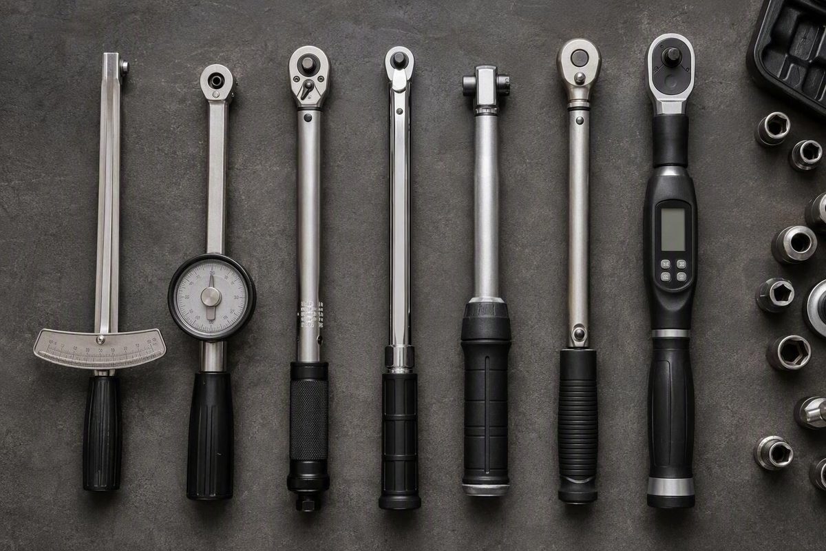
The main types of torque wrenches are beam, deflecting-beam, dial, click or micrometer-adjustable, split-beam, slipping, break-over, and digital or electronic. The useful distinction is how they behave: some continuously show applied torque, some signal when a preset target is reached, and some slip or change drive behavior to reduce further torque transmission.
Choose by matching that behavior—and the exact wrench’s documented range, operating direction, accuracy specification, head arrangement, calibration status, and data features—to the joint.
Related: Impact Wrench vs Impact Driver: Fastener Type Decides.
The main torque-wrench types at a glance
There is no definitive count of torque-wrench types because published guides mix different classification levels:
- Operating mechanism: beam, click, slip, break-over
- Readout: pointer scale, dial, electronic display
- Target adjustment: fixed, preset, micrometer-adjustable
- Head configuration: ratcheting, flex-head, interchangeable, open-end
- Power method: manual, hydraulic, battery-powered, multiplier-assisted
- Special application: no-hub plumbing, production assembly, joint inspection
For example, “preset” says that a target is established before use. It does not reveal whether the wrench clicks, slips, breaks over, or produces an electronic alert. Likewise, an interchangeable or flex head changes how the tool reaches a fastener, not necessarily how it senses torque.
A practical two-level taxonomy clears up the overlap:
- Classify the tool by behavior: indicating, signaling, or limiting.
- Identify the mechanism or configuration within that behavioral group.
Under this framework:
- Indicating tools continuously display applied torque.
- Setting or signaling tools announce that a preset threshold has been reached.
- Limiting tools slip, release, or change drive behavior near the target.
This is a practical selection framework, not a direct mapping to formal ASME type numbers. ASME B107.300-2021 covers mechanical hand torque tools, electronic torque instruments, and electronic torque testers, with further classifications inside those categories.
| Design | Behavior and feedback | Reading, release and adjustment | Data capability and typical use |
|---|---|---|---|
| Beam | Beam deflection moves a pointer across a scale | Continuous reading; no release; normally read to value | No inherent data storage; general work where the scale remains visible |
| Deflecting-beam | Beam-based mechanism gives model-dependent visual, audible, or tactile feedback | Selected-target indication; release and adjustment vary by model | Usually no data storage; beam-based preset tightening |
| Dial | Mechanical gauge displays torque throughout the pull | Continuous reading; no release; some models retain a finishing reading | Mechanical memory pointer on some models; monitoring, inspection, testing, or auditing |
| Click or micrometer-adjustable | Audible and tactile signal at a preset target | Usually no continuous reading or physical stop; commonly adjustable | Usually no data storage; routine maintenance and vehicle work |
| Split-beam | Distinct beam construction provides model-dependent preset feedback | Usually not continuous; adjustment, movement, direction, and storage requirements vary | Usually no data storage; repeated general-service tightening |
| Slipping | Mechanism slips near the setpoint | Physical reduction or interruption of torque transmission; fixed or adjustable | Usually no data storage; repetitive assembly where follow-through is a concern |
| Break-over | Drive behavior changes or is interrupted near the target | Movement, release, adjustment, and reset are model-dependent | Usually no data storage; assembly where pronounced target feedback is useful |
| Digital or electronic | Sensor measures torque; display and model-dependent alerts guide the user | Continuous electronic reading; programmable but not inherently torque-limiting | Model-dependent memory, angle measurement, identification, or export; guided or traceable tightening |
These are family-level descriptions, not promises about every product. Split-beam, preset, electronic, and break-over tools can differ substantially in adjustment method, direction rating, reset behavior, and release action.
Beam, deflecting-beam and dial wrenches: read the torque as you pull
A basic beam torque wrench has a load-bearing beam that bends under force. A separate pointer remains positioned over a calibrated scale, allowing the operator to read applied torque from the amount of beam deflection.
The wrench does not stop at the specified value. The operator must:
- Keep the scale visible.
- Apply force smoothly.
- Watch the reading rise.
- Stop at the required torque.
That makes grip position, viewing angle, access, and control important. A beam wrench may be inconvenient if the scale will be hidden or the working position makes it difficult to read accurately while pulling.
A deflecting-beam wrench is a distinct beam-based variant. Rather than operating only as an always-visible pointer scale, it may be set to provide visual, audible, or tactile feedback at a selected torque. Signaling and reset arrangements vary, so a deflecting-beam wrench should not automatically be treated as either a basic beam wrench or a split-beam model.
A dial wrench mechanically displays torque on a gauge throughout the pull. Some models include a memory pointer that remains at the finishing or peak reading after force is removed. That retained reading can help when the operator cannot watch the dial continuously.
Dial tools are used for torque monitoring, joint testing, auditing, verification, and quality-control work; Grainger’s torque-wrench guide describes continuous dial indication and memory-pointer use. Whether a particular wrench can validly measure peak, residual, reverse, breakaway, or loosening torque still depends on its documented capabilities.
Choose a continuously indicating wrench when seeing torque develop matters more than receiving one preset signal. It may suit investigating joint behavior, capturing a finishing reading, or working to different values without repeatedly changing a preset. Choose another mechanism if access prevents controlled movement or leaves the scale unreadable.
Click, micrometer and split-beam wrenches: a signal is not a stop
A click torque wrench is set to a target before tightening. When the threshold is reached, its internal mechanism produces an audible click and movement that can usually be felt through the handle.
The click is generally a signal, not an automatic stop. Continuing to pull can transmit additional torque and overtighten the fastener. Stop immediately at the first clear click rather than pulling through it or clicking repeatedly. SCS Concept’s comparison of click and slip tools likewise notes that torque can continue after the click point.
It is an adjustment method, not a universal synonym for every click wrench—and it is not interchangeable with “split-beam.”
Its adjustment controls, ratcheting action, operating direction, release movement, and storage instructions vary by model. Guidance written for a spring-loaded micrometer click wrench should not automatically be applied to every split-beam design.
Similarly, preset is not a complete mechanism description. A preset wrench may:
- Click at its target
- Slip near the target
- Change drive behavior through a break-over mechanism
- Produce an electronic alert
- Be fixed or adjustable by an authorized setting method
There is no supported basis for declaring click, micrometer-adjustable, or split-beam wrenches universally more accurate than one another. Compare the individual wrench’s accuracy specification, usable range, rated direction, calibration record, and applicable test conditions.
For routine automotive service, a click wrench or suitable split-beam model provides convenient feedback when tightening a fastener to a documented specification. Confirm the required value and units, use the intended grip area, apply force smoothly, and stop at the first signal.
Slipping and break-over wrenches: stronger protection against follow-through
A slipping torque wrench uses a clutch, roller-and-cam arrangement, or similar mechanism that slips near a predetermined threshold. Once it slips, further handle movement reduces or temporarily interrupts torque transmission at the fastener.
That is different from a conventional click wrench. A click alerts the operator but may continue transmitting torque. A slipping mechanism physically changes the drive path, which reduces overtightening risk when repetition or production pace makes an immediate response to a click less dependable.
It does not eliminate the risk.
Do not assume that every break-over tool pivots through the same angle or completely prevents further torque.
Before selecting one, verify:
- Rated torque range
- Fixed or adjustable setting
- Operating direction
- Reset behavior
- Permitted duty cycle
- Head and attachment restrictions
- Suitability for the joint and working torque
Digital and electronic wrenches: measurement, guidance and records
A digital or electronic hand torque wrench uses an internal sensor to measure applied torque and show it on an electronic display. Depending on the model, feedback may include:
- A numeric display
- LED progress indicators
- A buzzer
- Vibration
- Pass/fail prompts
Possible workflow features include programmable targets, stored presets, peak-reading memory, torque-angle measurement, operator or fastener identification, tightening-sequence guidance, software communication, and data export.
Not every digital wrench measures angle, stores readings, or connects to software. A torque-plus-angle procedure requires a model explicitly equipped and approved for angle measurement; a digital torque display alone is not sufficient.
For traceable production, a compatible electronic wrench may provide pass/fail guidance and export tightening records associated with a tool, operator, or fastener. Manufacturer guidance from Norbar identifies torque, angle, time, pass/fail status, and identification as possible smart-tool records. Those capabilities must be confirmed for the exact wrench and software combination.
Traceability and accuracy are separate questions. Electronic recordkeeping can support production documentation, but digital construction alone does not prove that a wrench is more accurate than every mechanical design. Accuracy must come from the individual model’s specification, test conditions, and calibration status.
An electronic hand wrench should also not be confused with:
- A powered torque multiplier that supplies output torque
- A hydraulic bolting tool
- An electronic torque tester used to check other tools
These products may use electronic components or displays, but they perform different jobs.
Specialty torque tools and head configurations
Some torque-tool labels describe a narrow application or how the tool reaches a fastener rather than how it measures or limits torque.
A no-hub torque wrench is a fixed-purpose tool for tightening specified clamps on hubless plumbing couplings. It is commonly supplied in a T-handle format. The wrench must match the coupling system’s specified torque rather than being treated as a general-purpose substitute; no-hub tools are described as specialty plumbing torque wrenches.
Hydraulic and multiplier-based tools belong to the broader controlled-torque landscape. They may suit large fasteners or torque levels that would require impractical handle length or operator force from an ordinary hand wrench. Selection and use require procedures appropriate to the exact equipment rather than instructions intended for a manual hand wrench.
An interchangeable, flex, ratcheting, or open-end head primarily changes access and attachment options:
None of those configurations alone establishes whether the wrench uses a beam, click, split-beam, electronic, slipping, or break-over mechanism.
Restricted access may justify a flex or interchangeable head, but confirm the permitted attachment, orientation, and geometry in the wrench manual. An offset attachment that changes effective lever length can change the torque delivered at the fastener. Do not assume that every extension or attachment affects torque in the same way.
Two wrenches with the same square-drive size can have very different ranges and capacities.
How to choose: match the mechanism, range and records to the joint
Start with the equipment or fastener specification, not the wrench type. Torque is rotational force—expressed in basic terms as applied force multiplied by effective lever length. The wrench must cover the required value in the correct units, operate in the required direction, and fit the available space.
| Task | Type to investigate | What still needs verification |
|---|---|---|
| Routine vehicle maintenance | Click or split-beam | Specified torque, range, direction, drive size, accuracy |
| Low-torque bicycle or small-fastener work | Compact beam, click, or digital | Low-end range, units, head access, calibration |
| Inspection or joint testing | Dial or suitable digital | Peak, residual, reverse, or breakaway capability |
| Repetitive assembly | Slipping or break-over | Duty cycle, reset action, setpoint control, joint suitability |
| Traceable production | Digital or electronic | Data fields, pass/fail logic, software compatibility |
| Restricted access | Flex-head or interchangeable-head tool | Approved attachment, offset geometry, direction |
| Large industrial bolting | Hydraulic or multiplier-based tool | Capacity and application-specific operating procedure |
| No-hub plumbing | Dedicated no-hub wrench | Coupling specification and required torque setting |
Selection criteria that matter
Check all of the following for the exact tool:
- Required torque and units
- Documented operating range
- Individual accuracy specification
- Calibration status and certificate, where required
- Rated tightening direction
- Drive size or head arrangement
- Access around the fastener
- Permitted attachments
- Duty cycle and frequency of use
- Joint criticality
- Consequences of overtightening
- Need for angle measurement
- Data and traceability requirements
The often-repeated advice to work between 20% and 80% of a wrench’s capacity is typical guidance rather than a universal rule. The exact tool’s documented operating range, accuracy statement, and calibration certificate take precedence. Norbar presents the 20%–80% range as a typical recommendation while also emphasizing range, accuracy, access, duty cycle, criticality, and data requirements.
A precise torque reading does not guarantee a precise clamp load. Applied torque controls preload only indirectly because lubrication, thread friction, surface condition, fastener material or grade, and joint design affect how much input torque becomes tension in the fastener. Follow the specified thread and lubrication condition; changing those conditions can change clamp load at the same wrench reading.
Short use checklist
- Confirm the specified torque and units.
- Select a wrench whose documented operating range covers the target.
- Verify its direction rating, calibration status, head, and attachment.
- Set or read the value carefully.
- Apply smooth force at the intended grip position.
- Stop at the required reading, click, slip, or break-over signal rather than continuing through it. Guidance for manual torque wrenches recommends smooth application and stopping immediately at the signal.
- Follow both the wrench manual and the equipment or fastener instructions.
For critical work, remove a wrench from use after a drop, overload, repair, or suspected inaccurate result until it has been handled under the manufacturer’s or applicable quality procedure. Manufacturer guidance advises against exceeding the rated maximum and recommends checking or recalibrating a wrench after events such as a drop. Calibration frequency should reflect use, environment, joint criticality, tool history, and quality-system requirements rather than one universal interval.
As a standards reference, ASME B107.300-2021 covers mechanical hand torque tools, electronic torque instruments, and electronic torque testers. ISO 6789 is commonly summarized as distinguishing indicating and setting hand torque tools. These frameworks are useful, but familiar retail names should not be mapped directly to ASME type numbers without the complete definitions and classification tables.
Choose by behavior before features: use beam or dial when you need to watch torque develop, click or another preset-signaling design when target feedback is sufficient, and a slipping or break-over mechanism when reducing operator follow-through matters. Consider a digital tool when angle control, guidance, or records are genuine requirements. In every case, verify the exact wrench’s range, direction, accuracy, attachments, calibration status, and instructions against the joint specification.
Frequently asked questions
Can a torque wrench be used to loosen a fastener?
Do not use a torque wrench as a breaker bar; forcing a seized fastener may exceed the wrench’s rated capacity before the fastener moves. Manual torque-wrench guidance specifically advises against breaker-bar use and exceeding the rated maximum.
How often should a torque wrench be calibrated?
There is no universal interval for every wrench and application. Base the schedule on the manufacturer’s instructions, frequency of use, duty cycle, environment, joint criticality, calibration history, and governing quality procedure.
Have the wrench checked sooner after a drop, overload, repair, exposure outside its operating conditions, or a result that appears inaccurate. High-use or critical-production tools may require shorter intervals than lightly used general-maintenance tools.
What is the difference between ft-lb, in-lb and N·m?
They are units of torque:
- ft-lb means foot-pound
- in-lb means inch-pound
- N·m means newton-metre
One foot-pound equals 12 inch-pounds. Midland Tool’s torque-wrench guide confirms the 1 ft-lb = 12 in-lb conversion.
Foot-pounds and inch-pounds belong to the inch-pound system, while newton-metres are the SI unit commonly used with metric specifications. Do not keep the same number when changing units: convert the value correctly, then confirm that the wrench is displayed or graduated in the required unit.