
How Big Is a #14 Screw—and Which Measurements Actually Matter?
One production wood-screw guide puts thread diameter at 0.235-0.246 in. and body diameter at 0.190-0.201 in., showing why measurement point matters.
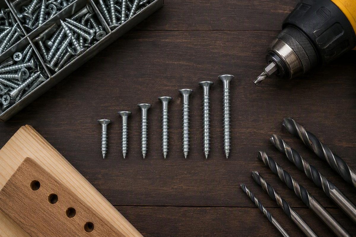
#14 Screw Dimensions at a Glance
A #14 screw is commonly described as approximately 1/4 inch, or about 6.3 mm, across the outside crests of its threads. This outside-thread measurement is called the major diameter.
The word approximately matters. Different charts publish different figures because they may cover different screw families, use rounded conversions, or group #14 with the nearest common fractional size.
| Reference or convention | Published diameter | Interpretation |
|---|---|---|
| General American screw-size table | 0.24 in.; 6.3 mm | Published thread-diameter values, with 1/4 in. shown as the nearest fraction (BS Stainless) |
| Wood-screw diameter chart | 0.242 in. | Source-specific major thread diameter for a #14 wood screw; 1/4 in. is the nearest fraction (Bolt Depot) |
| General chart grouping #14 with 1/4 in. | 0.250 in.; 6.35 mm | Nominal grouping or practical comparison rather than a universal measured diameter (Monster Bolts) |
These are not three equally exact measurements of one universal screw geometry. In particular, converting exactly 1/4 inch produces 6.35 mm, but that mathematical conversion does not prove that every #14 screw measures exactly 0.250 inch.
Practical answer: Use roughly 1/4 inch or 6.3 mm over the threads when you need a physical comparison or want to locate the right general category. Do not rely on that approximation alone when matching a nut, tapped hole, replacement fastener, pilot drill, or structural specification.
A bare #14 designation does not establish:
- Screw length
- Thread pitch or threads per inch
- Thread form
- Body or unthreaded shank diameter
- Head diameter or height
- Drive type or driver-bit size
- Pilot-hole, clearance-hole, or countersink size
- Material, coating, strength, or load capacity
- Required embedment, spacing, or edge distance
For a precise replacement, identify the screw family and measure the original fastener.
Why #14 Diameter Charts Show Different Numbers
Published values such as 0.24, 0.242, 0.250, 6.15, 6.3, and 6.35 mm do not necessarily describe the same measurement point or the same type of screw.
Some are rounded reference values. Some are direct conversions of a nominal fraction. Others apply to a particular screw geometry or use terminology such as shank diameter where another chart reports major diameter.
Before comparing two figures, ask:
- What screw family does the chart cover?
- Where on the screw is the diameter measured?
- Is the figure measured, nominal, rounded, or a nearest-fraction comparison?
- Which product specification or sizing convention applies?
The measurement points are not interchangeable
Several diameters may appear on one screw:
- Major diameter or thread diameter: The largest diameter across opposing thread crests. This is the usual measurement when discussing a screw’s outside threaded size.
- Body diameter: A source-specific measurement of the screw body. In the production wood-screw chart discussed below, it is identified separately from the outside thread diameter. Other references may use different terminology, so follow the accompanying drawing.
- Shank diameter: The diameter of a bare, unthreaded section where one exists. Some general tables use shank diameter more broadly, making the source’s diagram or glossary important.
- Minor diameter: The smaller diameter at or near the thread roots—the valleys between the crests.
A caliper placed across the outer thread crests will produce a different result from one placed across the roots, on a reduced body, or on an unthreaded shank. Those measurements answer different questions and should not be substituted for one another.
A production wood-screw guide illustrates the difference. For the #14 screws covered by that guide, the major or thread diameter is 0.235–0.246 inch, while the separately identified body diameter is 0.190–0.201 inch. The guide also warns that its production-screw geometry differs from traditional wood-screw geometry. (McFeely’s)
That range helps explain why an actual #14 wood screw need not measure exactly 0.250 inch. A nominal size category can encompass source- or product-specific geometry; it is not necessarily a promise that every part will equal the nearest common fraction.
Rounded conversions can imply false precision
One quarter of an inch converts mathematically to 6.35 mm. If a chart first approximates a screw as 1/4 inch, however, converting that approximation to 6.35 mm does not create a more precise specification.
Keep each figure attached to its original context:
- 0.24 inch is a published general thread-diameter value.
- 0.242 inch is a published wood-screw major-diameter value.
- 0.250 inch appears in charts that group #14 with 1/4-inch fasteners.
- 6.3 mm is a common metric reference for 14 gauge.
- 6.35 mm is the direct conversion of exactly 1/4 inch.
- 6.15 mm appears in one 14G table specifically as a rounded shank diameter, not as the universal major diameter of every #14 screw.
The table publishing the 6.15 mm shank diameter also gives 1/4 inch as the nearest fractional measurement and states that its millimeter figures are rounded to two decimal places. That terminology should not be generalized to every #14 thread. (Steelmasters)
The useful dimension therefore depends on the screw type, measurement point, applicable convention, and actual product data. A general chart can orient you; a fitted or engineered assembly requires the relevant specification.
What the #14 Designation Does—and Does Not—Tell You
The #14 identifies a nominal numbered size or gauge associated with outside thread diameter. It is not the screw’s length, and it does not automatically establish thread pitch.
Length, pitch, head style, drive, material, and other characteristics must be stated separately or obtained from the product description.
Reading “#14 x 2-1/2 in.”
This designation means:
- #14: Nominal screw diameter or gauge
- 2-1/2 in.: Stated screw length
It does not state the pitch, screw family, head profile, drive style, point, material, or coating. The applicable head convention determines where the stated length begins. The same diameter-and-length interpretation appears in a retailer’s “#14 x 2-1/2 inches” example. (DK Hardware)
Reading “14-10 x 25 mm”
This description contains three pieces of information:
- 14: 14 gauge
- 10: 10 threads per inch
- 25 mm: Screw length
The metric length does not necessarily mean that the thread itself is metric. Here, the gauge and threads-per-inch format remain imperial-style measurements even though the length is given in millimeters.
Some timber-screw descriptions omit the middle pitch figure and may appear as 14 x 25 mm or 14 x 1 in. In those cases, pitch must be obtained from the product information rather than inferred from the gauge. (Allfasteners)
What remains unknown with a bare “#14”
Even after identifying the approximate outside diameter, a buyer may still need to specify:
- Wood, machine, sheet-metal, self-tapping, self-drilling, or timber screw
- Thread pitch and form
- Full-thread or partial-thread construction
- Head profile and dimensions
- Drive recess and bit size
- Point or drill-tip style
- Length
- Material and coating
- Product standard
- Pilot-, clearance-, or tapping-hole requirements
Do not assume that #14, 14G, and 1/4 inch are universally interchangeable across countries, product categories, or standards. Similar diameter alone is insufficient when a screw must engage an existing internal thread or comply with an engineered connection specification.
That is not the same designation as #14 screw.
Dimensions Change with the Type of #14 Screw
There is no single complete set of #14 screw dimensions covering every screw family. The relevant dimensions change according to what the screw is designed to do.
Production wood screws
One specialist production wood-screw guide publishes the following source-specific #14 dimensions:
| Dimension | Published #14 range or limit |
|---|---|
| Major or thread diameter | 0.235–0.246 in. |
| Body diameter | 0.190–0.201 in. |
| Flat-head diameter | 0.452–0.507 in. |
| Pan-head diameter | 0.473–0.492 in. |
| Maximum pan-head height | 0.175 in. |
Source-specific production wood-screw dimensions: McFeely’s production-screw guide.
These figures apply only to the production wood screws represented by that guide. They are not universal dimensions for traditional wood screws, machine screws, sheet-metal screws, self-drillers, self-tappers, or timber screws.
The same guide assigns a #3 bit to its #14 square-drive screws. That is a drive specification for the square-drive products covered by the guide, not a rule for every #14 screw. A Phillips, slotted, hex, or other recess requires the driver specified for that actual head.
Machine screws
A machine screw must match both:
- Major diameter
- Thread pitch and form
For machine-thread replacement, do not stop after measuring approximately 0.24 or 0.25 inch. Determine the threads per inch, identify the applicable thread system, and compare the fastener with the governing specification or known-compatible mating thread.
Self-tapping screws
Gauge alone does not specify the point, pitch, required starting hole, material range, or installation conditions.
One listed 14G Type AB example has 14 TPI. That is a product-family example, not a default pitch for every #14 screw.
Self-drilling screws
Self-drillers have a drill-shaped point intended to make a starting hole within the product’s stated drilling capacity. The gauge does not reveal:
- Drill-point style
- Maximum drilling capacity
- Thread pitch
- Available threaded length after penetrating the material
- Product-specific installation requirements
Selected 14G self-drilling examples are listed at 10 TPI and 20 TPI, with different drilling capacities. Those alternatives demonstrate why pitch and drilling capability must be taken from the actual product listing rather than inferred from 14G. The Type AB and self-drilling examples are published together in the Allfasteners guide cited above.
Timber screws
Some labels state gauge and length without stating pitch.
Consequently, a timber-screw selection may require confirmation of:
- Pitch and thread pattern
- Point design
- Threaded and unthreaded lengths
- Head dimensions
- Pilot-drilling instructions
- Required embedment
- Material and application limits
Across every screw family, verify the actual product’s pitch, point, drilling capacity, head dimensions, available length, embedment requirements, and installation instructions.
How to Measure Diameter, Length, Pitch, and the Head
An unknown screw can often be identified for replacement with clean calipers, a thread-pitch gauge, and careful notes.
-
Clean the screw. Remove loose dirt, corrosion, coating debris, and trapped material where practical so the caliper jaws contact the metal consistently.
-
Identify the likely screw family. Note whether the fastener resembles a wood screw, machine screw, sheet-metal screw, self-tapper, self-driller, or timber screw. Examine its point, thread depth, threaded length, and head.
-
Measure the major diameter. Place the caliper jaws across opposing thread crests at the widest threaded section. Keep the jaws square to the screw axis. Do not measure only across the thread valleys or assume an unthreaded section equals the major diameter.
-
Check several positions. Measure near the upper, middle, and lower portions of the thread when wear or damage is present. Record consistent readings rather than relying on a burred starting thread.
-
Determine thread pitch. For an imperial thread, use a pitch gauge or count the threads over a known distance and express the result as threads per inch. For a metric thread, pitch is normally the crest-to-crest distance in millimeters.
-
Measure length according to the head style. - For a protruding head, measure from beneath the head to the tip. - For a flat or flush countersunk head, measure from the top of the head to the tip. - For a raised countersunk head, measure from the tip to the seating plane and exclude the raised dome. - For a set screw, measure end to end.
-
Record overall and threaded length separately. If the screw is partially threaded, record both measurements. Screws with the same nominal overall length may have different threaded lengths.
-
Measure the head. Measure a round, pan, or flat head across its widest diameter. Measure head height from the seating plane or base to the highest point as appropriate. For a hex head, measure across the flats rather than across opposing corners.
-
Identify the drive recess. Record whether it is slotted, Phillips, square, internal hex, external hex, or another style. A suitable driver should seat fully in the actual recess.
-
Record material clues and markings. Note the finish, visible corrosion, magnetic response where relevant, and stamped head or manufacturer markings. Treat appearance as an identification clue rather than conclusive proof of material.
Major diameter and pitch are both needed to characterize a thread, and head style determines the appropriate length convention. These measurement methods are summarized in Accu’s illustrated screw-measurement guide. (Accu)
Your identification record should include:
- Screw family
- Measured major diameter
- Threads per inch or metric pitch
- Measured overall length
- Threaded length
- Head profile
- Head diameter and height
- Drive recess
- Point style
- Material or coating
- Visible manufacturer markings
Diameter alone cannot reliably distinguish otherwise similar imperial and metric threads. For a precision internal thread, compare both diameter and pitch with the applicable specification instead of forcing a trial fit.
#14 Versus 1/4-20 and 1/4-28 Machine Screws
A #14 screw is often described as roughly 1/4 inch in diameter, but that does not make it universally equivalent to a 1/4-inch machine screw.
General conversion charts may group #14 and 1/4 inch at a nominal 0.250 inch or 6.35 mm. Wood-screw references, however, publish values such as 0.242 inch or a production range of 0.235–0.246 inch. Those figures arise from different conventions and screw geometries, not from one universal part specification.
Machine-thread designations explicitly combine diameter and pitch:
- 1/4-20: Nominal 1/4-inch machine thread with 20 threads per inch
- 1/4-28: Nominal 1/4-inch machine thread with 28 threads per inch
The 20-TPI and 28-TPI values belong to the listed 1/4-inch coarse and fine machine-thread designations. They must not be assigned to every screw labeled #14. The same conversion guide that groups #14 with 1/4 inch lists these separate UNC and UNF thread counts. (Monster Bolts)
A fastener that appears close in diameter may still have:
- The wrong threads per inch
- A different thread form
- Different major or minor dimensions
- A material-forming thread rather than a machine thread
- A product-specific fit that does not match the receiving thread
If initial engagement feels incorrect, stop rather than treating extra torque as proof of compatibility. For replacement in a nut or tapped hole, match the measured major diameter, pitch, thread form, and applicable product specification. Use “approximately 1/4 inch” only to narrow the search.
Pilot Holes and Countersinks: Useful Examples, Not Universal Rules
There is no single pilot-hole or countersink size for every #14 screw.
Hole selection can depend on:
- Screw family and thread geometry
- Root or body dimensions
- Point style
- Substrate
- Material hardness or density
- Grain orientation in wood
- Metal thickness
- Required thread engagement
- Head shape and diameter
- Product-specific installation requirements
A 14G wood-table example
One 14G reference gives the following source-specific values:
| Operation | Published example |
|---|---|
| Pilot hole in hardwood | 11/64 in. |
| Pilot hole in softwood | 5/32 in. |
| Countersink | 1/2 in. |
These values come from the Steelmasters table cited earlier. They are examples to use only where that table applies—not universal instructions for every #14 or 14G screw.
The 1/2-inch countersink must be checked against the actual head diameter, head geometry, desired seating position, and product instructions. Gauge alone does not establish the required countersink.
A different Type AB example
A separate 14G Type AB reference lists:
- 4.9 mm as a softwood pilot
- 4.80–6.00 mm as a predrilled or punched-hole range for metal
Those figures belong to the cited Type AB screw category and its stated applications. They should not be averaged with the wood-table values or repurposed as general guidance for every #14 screw. The Allfasteners guide also cautions that its Type AB hole dimensions are guidance and that application conditions can require different values.
The contrast is the important point: the same broad gauge label can appear on screws that form, cut, drill, or engage material differently.
A practical decision sequence
Before drilling:
-
Identify the screw type. Determine whether it is a conventional wood screw, production screw, Type AB self-tapper, self-driller, timber screw, or another design.
-
Identify the substrate. Distinguish among solid wood, engineered board, plastic, and the relevant type and thickness of metal.
-
Consult product-specific data. Look for pilot-hole, tapping-hole, clearance-hole, countersink, drilling-capacity, and installation information for the actual screw.
-
Check the head geometry. Match the countersink to the real head rather than selecting it from gauge alone.
-
Test representative scrap when appropriate. Reproduce the material, thickness, grain direction, edge position, driver, and installation method as closely as practical.
-
Inspect the test result. Check whether the screw advances and seats as intended without obvious damage or looseness. Treat the result as an application check, not as a substitute for required engineering data.
For structural, safety-critical, or tightly toleranced work, use the applicable standard, approved design information, and actual manufacturer specifications. A generic pilot-hole chart does not establish load capacity, minimum embedment, spacing, edge distance, or suitability for a critical connection.
A Practical Checklist for Selecting or Replacing a #14 Screw
Use this checklist before purchasing or installing a screw marked #14 or 14G:
- [ ] Identify the screw family. Is it a wood, machine, sheet-metal, self-tapping, self-drilling, or timber screw?
- [ ] Measure the major diameter. Measure across opposing thread crests rather than relying only on the approximate 1/4-inch comparison.
- [ ] Match the pitch. This is essential when the screw enters a nut, tapped hole, threaded insert, or existing internal thread.
- [ ] Confirm the thread form. Similar diameter and pitch do not by themselves establish compatibility across every screw system.
- [ ] Choose the correct length. Apply the correct convention for protruding, flush countersunk, raised countersunk, or headless screws.
- [ ] Record threaded length. This matters when comparing partially threaded products.
- [ ] Check the head. Verify its profile, diameter, height, bearing surface, and countersink geometry.
- [ ] Match the drive. Confirm the recess and driver-bit size from the actual screw or product information.
- [ ] Verify the point and drilling function. Do not assume that every self-tapping screw is self-drilling.
- [ ] Check the material and coating. Select them for the intended environment and product requirements.
- [ ] Confirm pilot and clearance holes. Use data for the actual screw design and substrate.
- [ ] Confirm the countersink. Match it to the actual head rather than applying a generic #14 value.
- [ ] Review installation requirements. Check drilling capacity, embedment, spacing, and edge-distance requirements where applicable.
- [ ] Verify suitability for the intended load. The #14 designation alone communicates no load rating or structural approval.
The buying rule is straightforward: use “approximately 1/4 inch” to locate the likely shelf, catalog filter, or general category. Then use type-specific dimensions, measurements, and manufacturer data to confirm fit.
Frequently Asked Questions
Is a #14 screw exactly 1/4 inch in diameter?
Not universally. A wood-screw chart lists a #14 major thread diameter of 0.242 inch, with 1/4 inch identified as the nearest fractional measurement. (Bolt Depot)
A production wood-screw guide gives a 0.235–0.246-inch major-diameter range, while some general charts group #14 with a nominal 0.250-inch size. Treat 1/4 inch as an approximation, nearest fraction, or nominal grouping unless the applicable product specification says otherwise.
What is the metric equivalent of a #14 screw?
The usual quick comparison is about 6.3 mm across the outside threads. One American screw-size table publishes #14 as 0.24 inch or 6.3 mm, with 1/4 inch as the nearest fraction. (BS Stainless)
Some charts show 6.35 mm because that is the direct conversion of exactly 1/4 inch. Another 14G table gives 6.15 mm specifically as a shank diameter. These values are not automatically interchangeable specifications.
What does #14 x 2-1/2 inches mean?
It means a screw with a #14 nominal diameter or gauge and a stated 2-1/2-inch length. It does not state thread pitch, screw family, head style, drive type, material, or coating. (DK Hardware)
For a protruding head, length is generally measured from beneath the head to the tip. A flush countersunk screw is measured from the top of the head to the tip.
What thread pitch does a #14 screw have?
There is no universal pitch for every #14 screw. Pitch depends on the screw family and actual product specification.
Selected products illustrate the variation: one 14G Type AB example is listed at 14 TPI, while selected 14G self-drilling examples use 10 or 20 TPI. Separately, 20 TPI and 28 TPI identify listed 1/4-inch coarse and fine machine threads; those values do not automatically apply to a #14 screw.
Measure an unknown thread with a pitch gauge or count its threads over a known distance, then compare the result with the applicable specification.
What size pilot hole should I drill for a #14 wood screw?
There is no universal #14 wood-screw pilot hole. One 14G table lists 11/64 inch for hardwood and 5/32 inch for softwood, while the separate Type AB reference gives a 4.9 mm softwood pilot. These figures apply to different source-specific guidance and should not be blended into one recommendation. (Steelmasters)
Identify the exact screw and substrate first, then follow the applicable product data. For structural, safety-critical, or closely fitted work, the governing standard and manufacturer’s specifications take precedence over a generic chart.
A #14 screw is therefore roughly 1/4 inch or 6.3 mm across the outside threads, but that approximation is only a starting point. Reliable selection requires the correct screw family, measured major diameter and pitch, the proper head-based length convention, and product-specific head and drilling dimensions.